Up until now the APRS Tracker has been assembled on a breadboard in a rather large enclosure (see below). While convenient it is not very practical. So . . . lets put this into a small box:
Plan
Using a blowup of the RS PCB that would fit into the box, layout where everything will go / fit. This will take a bit of work to get the blowup to represent the actual board but will save time and perhaps your box when you start toe cut. Part of my blowup diagram can be seen under the box in the Fig 1.
Cut
Fig 1 PCB fit and Holes in box
(Fig 1) Once you have the layout finalized it is time to make some holes. A ‘Dremel’ tool with various bits will be a big help. Talk you time, Here are the parts placement and cuts:
- Upper right: The black cube is the RJ-45 jack on the SparkFun PCB, tucked under the PCB. It will be glued to the Main PCB with the connections coming up through the PCB holes.
- To the left is the USB Micro-B SparkFun PCB. This too will be glued to the Main PCB with some glue added around the actual connector for added strength.
- On the left side is the GPS Receiver with the antenna cut through the box. While the antenna should face up it can be inside the box. It does look cool sticking out and will get protected with clear tape when finalized.
- On the bottom is the push button rotary switch.
Add components (Fig. 2)
- A 10 position stackable header has been added to accept the
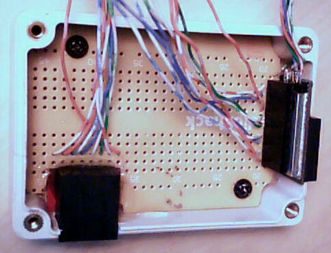
Fig.2 GPS module and TFT Display jack
TFT Display pins. The height was adjuste with a small spacer at the bttom of the header. This puts the display at a good height to clear the RJ-45 jack and the transformers (still to come)
- 10 wires have been added to the header, the display only needs 9, to allow some flexibility in placing the display. This will be finalized before solder and the extra lead cut off one end or the other.
- Two screws were added to hold the board in the box.
- The RJ-45 jack on its Sparkfun PCB has been epoxied to the board.
- The GPS unit is a tight fit at the top of the board behind the stackable header.
Now fit in the transformers etc.
Fig. 3 Wiring 101
Using the enlarged layout, visible below the W2DEN APRS Tracker carefully layout where the components will go. This will take some trial and error to fit everything into the case.