W2DEN’s APRS Tracker to Radio Interface
OK… you should have your GPS up and running. The next phase is to make an interface (I/O) between the GPS and the radio. Hopefully this will be universal for most rigs. The initial design comes from interfaces for a Kenwood HT like the TH6a or a Baofeng. Both use similar dual phono plugs (3.5 and 2.5 mm) for their external mic, ptt and speaker connections.
Here’s the circuit: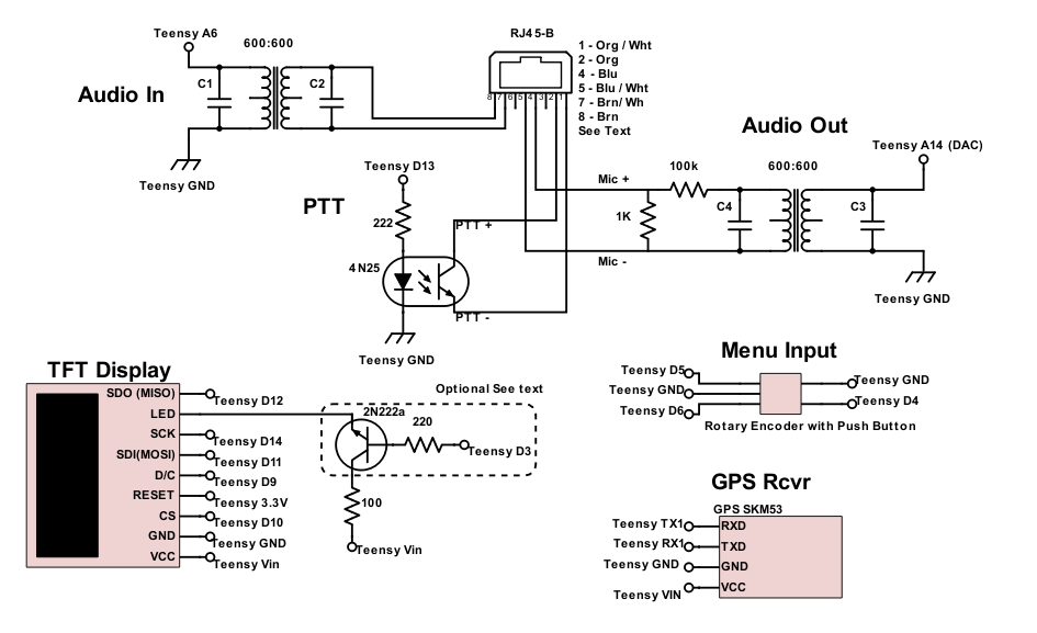
NOTES:
- 2N222 LED switch is optional. TFT LED lead can be connected to Vin through a 100 ohm resistor
- the rotary encoder only needed for V2 “with menu”
- C1 – C4 added as RF bypass. Kenwood HT insisted on blanking the screen on xmit. These caps removed that problem. Actually think c3 did the trick.
- Added audio input.
Thanks to the great DigiKey SchemeIt app ( Link ) that was used to create the this schematic.
PTT
Most published Arduino based GPS trackers use a MOSFET to key the rig. Based on soundcard interfacing in other posts here at N4SER we will go against the ‘norm’ and use an optical isolator. The reason is to isolate the rig from the computer (Teensy) to prevent ground loops. Ground loops can be an issue when two devices attached to each other are using different power supplies and can usually be eliminated by physically separating the devices using optical isolators and transformers.
Any attempt at a ‘direct’ PTT connection using a 2N222 transistor caused feedback most likely due to a ground loop. This was consistent with what was found construction a sound card interface.
. . . the radio and computer, be it a PC or a Teensy, must be isolated from each other.
Audio feed: Teensy to Microphone Connection
This circuit followed previous work on sound card to radio interfaces utilizing a 1:1 (sold as 600:600) ohm transformer for isolation, and a voltage divider to reduce the Teensy’s output to microphone levels. The resistor values were determined experimentally using the fabulous ‘Soundcard Scope’ by Christian Zeitnitz. There is the link to the web site. ( Link ) The voltage divider with a 3.3 v input, from the Teensy will result in a maximum output of 33 mV. This falls below the 80 mV maximum Kenwood specs for their microphone input. These values may need to be tweaked a bit but theses seem to produce a clean signal. A pot could be substituted for the divider and adjusted accordingly.
Squelch Detect: Speaker (radio audio) to Teensy
This circuit is optional added in v 2.02. In order to avoid transmission collisions it is a good idea to monitor the radio’s speaker output and only transmit when the radio’s squelch is not opened by a transmission from another APRS radio. This is accomplished by setting the radios’ squelch so other stations open (break) it and it silences the speaker output when no other radios are heard.
The Tracker ‘listens’ to the radio’s output and will only transmit when no other station is heard, the squelch is closed, the speaker is quiet. The level is a user adjustable field in the AX.25 menu.
The Squelch Detect can be disabled by setting the value in the menu to 0 (zero).
RJ-45; Some Information
The schematic above shows an RJ-45B connector to connect to the radio. This follows the previous post on a digital interface by KK7UQ (Link). Details on creating the actual Cat 5 cable can be found in the Digital Interface II manual (KK7UQ Interface manual). Using this scheme will allow you to use the same cable for digital modes such as PSK using the ditial interface or as an APRS tracker. Another advantage to the RJ-45 is that there are 4 pins open for additional connections, perhaps the radio’s audio out for a speaker in the APRS tracker or a squelch control for transmit.
NOTE: be sure and wire this as a RJ-45B with Org / Wh as pin 1 and Org as pin 2. There are lots of websites explaining the difference between the A and B RJ45 wiring scheme.
Of course other jacks can be used here. An 1/8″ stereo jack with the mic and PTT ground connected will work just fine.
The APRS Tracker to Radio Cable
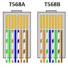
Cat 5 568 A & B
To use the RJ45 radio interface jack you will need a piece of Cat 5 cable with an RJ45 plug on one end.
Take an old cable and clip off one plug or cut one into whatever length you want or make your own if you have a crimper. Just keep the length under 24 inches.
Here’s how to connect it to the radio:
- Determine if RJ45 plug is wired as an A or a B :
- The plug will have 8 wires. One end will always be brown, the other end determines if it is A or B.
- Orange / White it is a RJ45B
- Green / White it is an A
- the T568A / B is the EIA standard designation for the plugs.
- Wire the ‘cut’ end as follows:
| RJ45A | RJ45B | Radio |
| Grn/Wht | Org/Wht | PTT Ground |
| Grn | Org | PTT + |
| Blu | Blu | Mic + |
| Blu/Wht | Blu/Wht | Mic – |
| Brn | Brn | Speaker + |
| Brn / Wht |
Brn / Wht | Speaker – |
Teensy Tracker to Radio examples:
We’ll assume that the Cat 5 cable you are using is wired on the Tennsy tracker end as a B connection. The first pair is Orange, Orange / White. If you are using “A” wired cables then substitute Green, Green / White for the Orange pair.
Kenwood TM-281A
2 M 65w mobile radio. RJ-45 mic connector. No speaker out in the mic connector.
Wire for PTT and Audio (mic) in. Cat 5 “B” cable (first pair orange)
| Cat 5 wire | Function | RJ-45 Mic connector |
| Orange | PTT | 4 |
| Orange/White | PTT Gnd | 3 |
| Blue | Mic+ | 6 |
| Blue/White | Mic- | 5 |
Kenwood TH6a HT Also BoaFeng HTs
This has been tested on the Kenwood TH-6a. A 5 watt 3 band (144/220/440) HT.
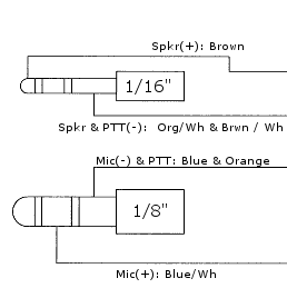
Mic/speaker connection is a dual phono plug 1/8″ / 1/16″. This connector does not appear to be commercially available.
Assume a “B” cat 5 cable with the first pair being orange / orange/White.
Two separate phono plugs will be needed, 1/8″ and 1/16″. look for plastic or metal connectors with a recess, see below.
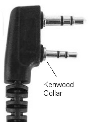
NOTE: The Kenwood dual jack connector has ‘collars’ around each connecor that fit into small indents in the radio around the mic and speaker jacks. This allows the OEM dual connector to fit tight against the body of the radio. Standard phono plugs may need to be trimmed to fit tight enough against the radio. If you find poor connections, mic plugs falling out or strange changes to the radio like changing bands then this may be your problem. The two connectors need to fit completely into the plugs. A light tug should not remove them.
This supposedly works on most BaoFeng HTs. Not sure about the recessed issue mentioned above but it should be considered.
Next will be some testing. Actually this has been ‘tested’ throughout the development but thought is would be easier to follow if every phase had its own post.
| << Previous: GPS | Next: Testing >>> |