 The Umbrella
This post describes a simple, easy to make and erect portable vertical antenna for the low bands (160, 80 and 40M). {ed. 80, 40, 20 and 15M were proven at FD 2018} This one is 30 feet high with a unique top hat, utilizing an SG-230 Smartuner and a single elevated radial. It has some ‘gain’, in the direction of the radial, and a good amount of vertical radiation for NVIS.
The use of a top hat was found to be the most efficient way to move the current up the antenna and to raise the radiation resistance, which for an 80M antenna only 30 feet long can be very low. The use of a mid-point loading coil was investigated but it was not as effective as the top hat and would be quite unruly at the required 40+ uH for 80M
While the SG-230 tuner is an ideal solution to tuning the antenna. A base load would accomplish the same result on 80, 60 and 40M. Once the antenna is more than 1/4 wavelength you will need to work out the base matching network.
What follows are guidelines from lessons learned. Adapt the design to fit your needs and equipment.
The antenna was demonstrated at the 2018 Sarasota Emergency Radio Club Field Day.
FIELD DAY UPDATE: This antenna was deployed with great success during Field Day 2018 at the Sarasota Red Cross. Call sign used was N2SER, operator: W2DEN Logger: Net N2RDX
A second ground 33 ft. (40M 1/4 wave) radial was added ending 10 feet to the left of the 80M radial. Not sure if it helped. Antenna patterns are almost identical with or without the second radial.
Over 100 CW QSOs were completed on 80, 40, 20 and 15 meters from Maine to Western Washington to Southern California, using 100 Watts. The antenna would not tune on 160M or 10M, those bands were not explored. The 15M QSO with California late Sunday morning was a highlight QSO.
Conclusion: This is a very valid portable HF antenna. While there were contacts with all three Florida sections (NFL, SFL and WCF the NVIS usefulness still needs to be determined.
Jump to the Build It instructions ( click )
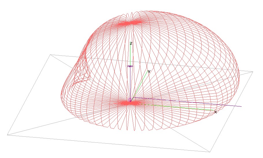
Here’s the 3 D far field pattern.
- X Y Z axis are Green
- The antenna is in Purple with the single elevated ground wire running down the X axis.
- The far field pattern @ 80M is in Red.
- The Magenta circle is the feed point I=30-j 486.
 A look at the current, in Green. Note how the top hat pulls the current up to the top of the antenna.
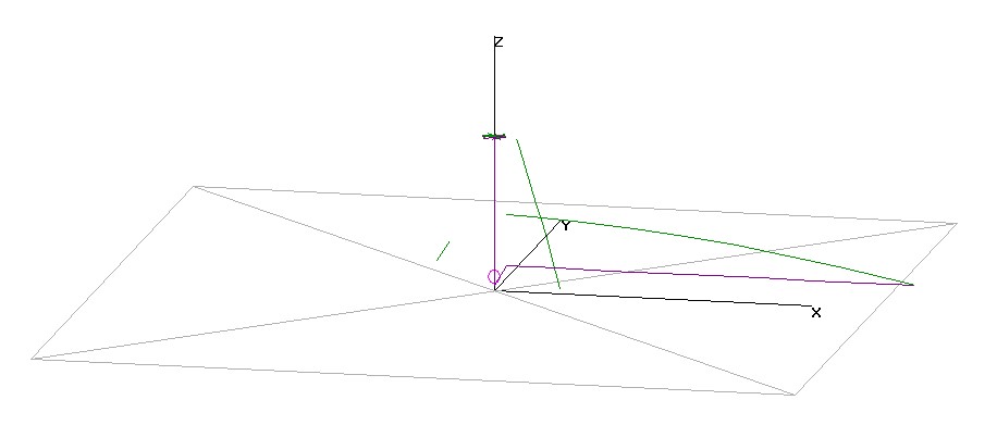 Let’s build it:
Parts list:
- Push up 32 foot mast. I used a Max-Gain Systems MK-6 Standard ( Link )
- Substitute any push up mast. metal can be used but it must be insulated from the ground.
- 32 feet is based on the mast I had. Shorter will decrease the radiation resistance, longer will be harder to manage.
- Guys for the mast.
- I prefer to guy the bottom section to give a stable platform to work from then every other section. 3 guys at each level for a total of 3 levels, 9 guys.
- You must use cordage that will not stretch. Nylon is out. Use Dacron or a poly cord. Everbilt 5/32″ polypropylene works perfect. Cheap, strong, neon so it is visible and is easy to tie and untie knots.
- Antenna wire: ~ 30 feet. Almost any wire will do. Insulated, stranded core works perfectly somewhere around 14 gauge.
- Ground Wire: 66 feet of the same wire is perfect for 80M. This will work on other bands or you can switch wire lengths as you switch bands. it will make a difference in the radiation resistance, antenna pattern and SWR.
- Base Load: Here I cheat and use an SGC SG-230 Smartuner.
- The tuner was purchased for portable and SHARES work and have never regretted it. Made specifically to tune non-coax loads it fits almost every portable operation I can think of.
- Other tuners may work just as well. if you have one, try it…. Yes, you want the tuner at the base of the antenna if possible.
- Coil (inductor), a ‘normal’ base load will also work just fine. Large diameter with thick wires. Find a match and add a tap so band changing is easy.
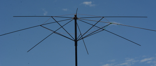
- Top hat:

- Here is where this becomes fun, and different. The tophat is an umbrella. I used a $6 cheapo from Walmart.
- Ed. Note the rust on the sanded metal. It has only been 2 weeks. A spray of clear lacquer would help.
- Requirements:
- at least 4 foot in diameter.
- metal spokes and main shaft.
- light weight, it must be supported at the top of your mast.
 Preparation:
- Remove the cloth and any handle.
- Disassemble the spokes.
- Why? many umbrellas have double spokes. this is unneeded weight for a top hat. a total of 8 spokes is more than you will need. and we will solder the spokes and do not want to melt the spoke hub.
- You will need to determine just how to do this. usually there is a wire that wraps around the spokes at the top and on the slide (the part you push up to open the umbrella). Untwist or cut this wire and you will have all the spokes in your hand.
- Solid picture wire is a great replacement for the wire holding the spokes to the hub.
- Solder a piece of ~ 4″ of light gauge, stranded wire to the top of each spoke. Just below where it attaches to the hub.
- Tin the top of the support mast above the hub.
- You will need to sand the paint off the metal before soldering.
- Re-assemble the spokes to the hub.
- This is tricky. Use tape and elastic bands to help hold the spokes in position as you thread in the new wire and twist it back tight.
- Careful here it is real easy to break the wire when twisting it tight…

- You only need 8 spokes. 4 will work if you need to reduce the weight.
- Now solder the spoke wires to the support post.
- Solder your antenna wire, the 30 foot from above, to the bottom of the umbrella post.
- You now have a 30 foot antenna with a top hat. Good stuff!
- I added a ring of wire around where the spokes joined the part that slid up and down to keep them in alignment if it gets windy. the following pictures will help show that.
- Ed this wire en-route to Field Day. A green garden wire fixed the mechanical issue (you can see it in the folded picture) . No attempt was made to re-solder the wire. Not sure it would matter.
- The top hat can then be Velcroed to the top of your mast before pushing is up.
- Run the ground wire from the base of the mast up to about 5 or 6 feet above ground and stretch it out in the preferred direction.It should NOT touch the ground.
- If you are using the SG-230 attach the antenna lead to the positive and the ground wire to the negative.


That’s about it……. Good luck.
4NEC2 NEC file is attached