This is part three of the series on Digital Communications.
In this article: KK7UQ the Gold standard, Why it is a good design, Changes, Simplified Schematic, Bells and Whistles
The Gold Standard (KK7UQ Interface Model II):
A number of years ago Clinton Hurd (KK7UQ) designed and sold this interface as a kit. It was easy to build and fit very nicely into an Altoids box. Unfortunately the kit is no longer available. Here is a copy of the manual (KK7UQ Interface manual) it includes a complete explanation of the circuit and the interesting radio to interface scheme he uses. Your Elmer has one of these original kits and has created a modified (simplified) version used for portable use.
Why this is a good interface design:
- 100% isolation between the radio and the computer.
- Audio transformer isolate the sound-card signals.
- Solid state relays isolate the PTT and FSK lines.
- Includes capability to ‘key’ the rigs FSK input as well as PTT
- This second line can also be used to key the rigs CW line instead of the FSK line allowing computer generated CW to utilize the same I/O.
- The dual color LED indicates which line is ‘keyed’.
- Easily configured for multiple rig.
- KK7UQ used an RJ45 jack for all of the radio interface wires.
- A length of CAT 5 cable then connects the radio to the I/O.
- Build a different CAT 5 cable for each radio and switching radios is as easy as plugging a different CAT 5 cable into the I/O. Very neat solution.
Changes:
- Replace the two solid state relays with optical isolator such as the 4N25.
- Remove the audio output circuit. It just isn’t needed.
- Remove J4, not needed.
- Remove SW1 and replace it with a simple STSP switch between the Dual color LED and J1.
- U2 the second keyed line is optional.
- If you plan on using traditional FSK or computer generated CW then this second keyed line will be useful. For most it is not needed.
- For single radio installs eliminate the J45 . Cat 5 cable interface.
- It is a unique solution but not needed for a single radio use.
Simplified Schematic:
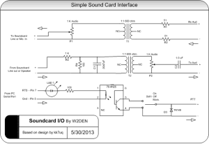
 This is the basic interface with a single control line (PTT) and no jacks.
- T1, T2 600 ohm 1:1 transformer: Mouser 42TL016-RC. May be available at Radio Shack
- P1,P2 1 K audio taper: Mouser 313-1520F-1K
- LED1: any color LED
- U1: Optical isolator. 4N25 typical.
- SW1: SPDT center off. Can have one side as momentary for tuning.
- All resistors 1/4 watt
This schematic is the starting point for just about every digital interface. It can be constructed on a small piece of perforated breadboard and have shielded cables connected to the radio and computer.
Radio Connections can be to the speaker jack and microphone jack or preferably to the radios accessory jack. This allows use of the radio’s speaker and microphone and will provide a constant level signal from the radio to the computer. Most modern radios are equipped withe some form of an accessory jack where audio in and out are available.
Bells and Whistles:
For a single radio / computer installation the circuit shown above, hard wired to the radio and computer will make the perfect digital interface. The circuit described in KK7UQ’s manual has a few additions that just may interest you:
- Jacks: 1/8″ stereo phono jacks can be added to the sound-card and serial port connections to the interface. Wire the (+) lines to the ‘tip’ or center conductor.
- RJ45: The use of an RJ45 (8 connector network jack) will make moving the interface between radios a snap. ow to wire the jack and utilize CAT 5 cabling is covered in the attached manual. This is a neat way of making the interface portable. But, for the cost why not just make more than one?
- Dual control or key lines: If you wish to also operate FSK or CW from the same computer the addition of a second control line will be needed. This is easy to do with a second 4N25. The circuit is part of the origianl KK7UQ’s design.
- What else???