This is not my idea. It is demonstrated on a number of sites. This originated some time ago and sat until the latest (6/18) 6M opening and when I had time to work on it. Now it is proven. This would make an ideal portable 6M antenna.
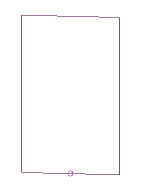
A full wave loop has an impedance of ~100 Ohms. Shorten the top and bottom and add to the sides and the impedance changes to 50 Ohms. Bingo!
I made a few 6M FT8 QSOs with this antenna at ~ 10 feet, as modeled, into the Midwest.
Top and bottom cross members are ribs from an old beach umbrella, center pole a 2″ pvc pipe… this is a temporary antenna. Will put it up when 6M is active.
The antenna analyzer results at dimensions of 240″ set 40″ x 80″”
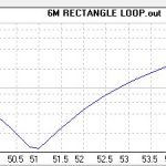
- SWR: 2:1 range 49.8 MHz to 52.2 MHz. SWR 1:1 52.20 MHz.
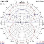
This antenna is horizontally polarized.
The antenna was designed for the bottom of the band for CW and other digital modes.
3 Thumbs, click for full sized graphs:
These are from 4NEC2. A little tighter than the actual antenna, prbab;y looses not accounted for in the model.
The NEC (4NEC2) file for this antenna is attached.


